STM32F0xx Development – Part 1: PCB
Overview
I decided to try my hand at developing a distributed I/O system based on the STM32F0xx MCU.
The goal was to create a small, flexible board that could be used in a variety of automation or control scenarios, while keeping the cost low and the design relatively simple.
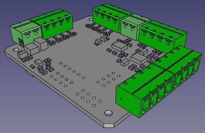
STM32F0 ADIO PCB
For this design, I chose the STM32F030 MCU for two main reasons:
- It’s cheap — around $1 USD.
- It has excellent Rust support, which makes it particularly attractive for embedded experimentation.
The board also includes several configurable options using solder bridges, allowing the same PCB to be adapted for different use cases. I’ll cover these options throughout the post.
Digital I/O
The board supports 8 digital channels, each of which can be configured as either an input or an output.
Inputs
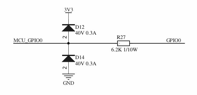
All digital inputs can accept voltages in the 5–30V range.
Outputs
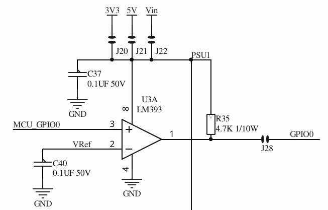
Four of the outputs use an LM393 comparator with a selectable output voltage range.
The remaining four outputs use an LM393 to drive a 200mA push-pull transistor output, also with a selectable voltage range.
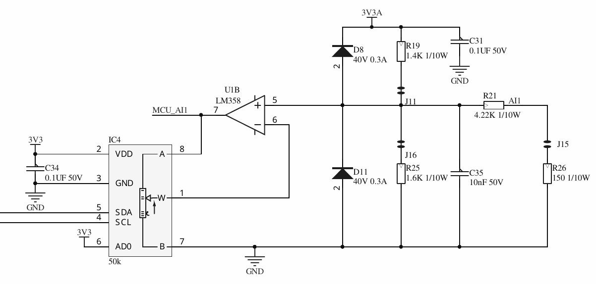
Analog I/O
The board includes four analog inputs, each supporting:
- ±10V input
- 4–20mA current loop (selectable)
Two of these inputs also feature controllable gain amplifiers, allowing for additional flexibility depending on the signal being measured.
Communication
Wired
- Dedicated RS485 interface
Wireless
Interfaces are provided for several inexpensive (≈ $1 USD) wireless modules commonly found on AliExpress and similar platforms:
- ESP-01 – Wi-Fi
- NRF24L01 – 2.4GHz transceiver
- RA-01 – 433MHz transceiver
PCB Dimensions
The PCB measures 50 × 60 mm.