Industrial Backplane
Overview
Decided trying my hand at creating a modular industrial backplane, the idea here is creating a pluggable system with a variety of different modules. The modules in this case could be different MCU modules with options for say faster or slower MCU’s or different logic levels for Input/Outputs.
Here are some 3D models of the first few boards I am getting made.
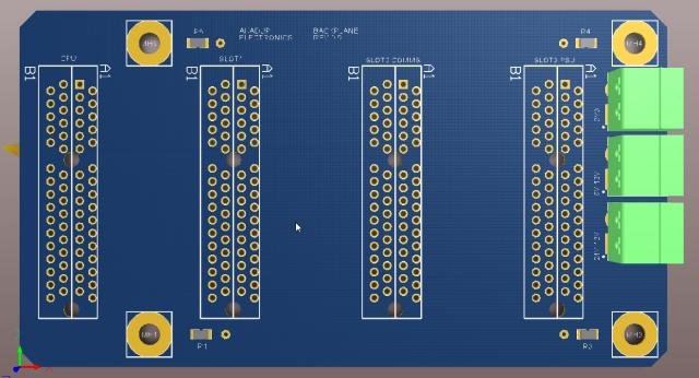
Backplane PCB
This board is essentially the main component all other boards will plug into.
Some features I tried to nail on this one:
- Allowed for up to 4 boards to be plugged in.
- Each slot is addressable.
- Provide connectors for 24V, 3V3 and 5V to be connected directly into the backplane (This could be replaced by a plug in board).
By convention the CPU will be plugged into slot 1 and the PSU will be plugged into slot 4 though this is just by convention and allowed space the backplane board have none of these restrictions built in.
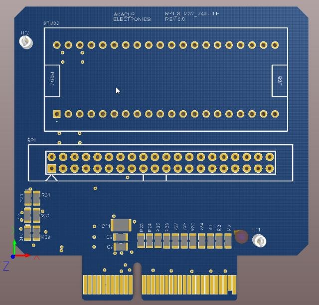
CPU PCB (RPI and STM32)
This is a board specifically designed for Raspberry Pi and STM32 based “Blue Pill” to interface with the backplane. I however imagine there will be a CPU board designed for each SBC/Microcontroller that needs to be interfaced with the backplane.
Some features I tried to nail on this one:
- Allow the controller to read what it is. This is done via an EEPROM chip.
- Expose all the low level peripheral(SPI, Serial, PWM etc) to the rest of the backplane.
By convention the CPU will be plugged into slot 1 and as explained above the backplane has no restriction that forces this other than physical space.